A3144 Hall effect Sensor
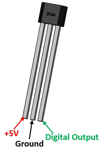
Pin Configuration
|
No: |
Pin Name |
Description |
|
1 |
+5V (Vcc) |
Used to power the hall sensor, typically +5V is used |
|
2 |
Ground |
Connect to the ground of the circuit |
|
3 |
Output |
This pin goes high, if magnet detected. Output voltage is equal to Operating voltage. |
Hall-effect sensor Specifications
- Digital Output Hall-effect sensor
- Operating voltage: 4.5V to 28V (typically 5V)
- Output Current: 25mA
- Can be used to detect both the poles of a magnet
- Output voltage is equal to operating voltage
- Operating temperature: -40°C to 85°C
- Turn on and Turn off time is 2uS each
- Inbuilt reverse polarity protection
- Suitable for Automotive and Industrial Applications
Note: To know why these parameters are important read further. Also the A3144 hall effect sensor datasheet can be found at the bottom of the page
Alternative Digital Hall-effect Sensors
A3141, A3142, A3143, US1881, OH090U
Other Analog Hall-effect Sensors
A1321, A1302, SS495B, ASC712
Where to use hall-effect sensor
A hall-effect sensor as the name suggests works with the principle of hall-effect and is used to detect magnets. Each side of the sensor can detect one particular pole. It can also be easily interfaced with a microcontroller since it works on transistor logic.
So if you are looking for a sensor to detect magnet for measuring speed of a moving object or just to detect objects then this sensor might be the perfect choice for your project.
How to use Hall-effect sensor
There are two main types of hall-effect sensor, one which gives an analog output and the other which gives a digital output. A3144 is a digital output hall sensor, meaning if it detects a magnet the output will go low else the output will remain high. It is also mandatory to use a pull-up resistor as shown below to keep the output high when no magnet is detected.
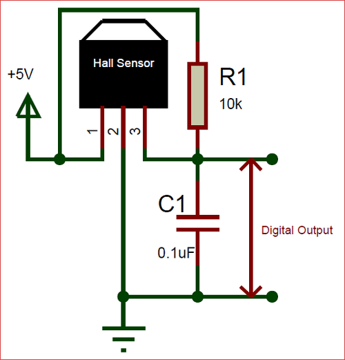
In the above circuit diagram the resistor R1 (10K) is used as a pull-up resistor and the capacitor C1 (0.1uF) is used to filter any noise that might be coupled with the digital output.
Applications
- Used to detect magnets(objects) in automation systems
- Used in magnetic door alarm system
- Measure speed in automobiles
- Detect the pole of magnets in BLDC motors
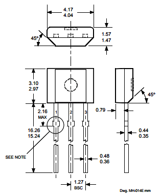
2D Model of A3144 (Through hole)